Commercial fiber infrastructure
Fiber Optic Cabling Installation in Nashville
Plan backbone and longer-distance links around the route, strand count, fiber type, termination hardware, connector requirements, active equipment, testing, and future capacity.
Infrastructure scope
Fiber selected for the actual link
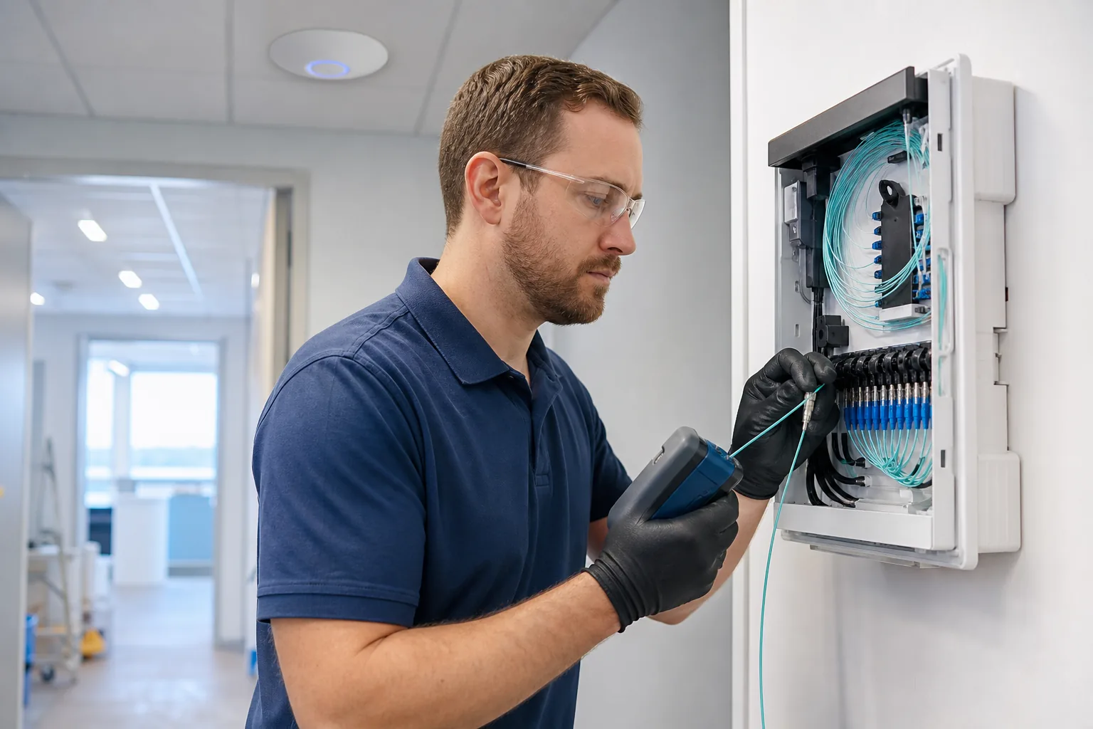
Fiber optic cabling can connect network rooms, buildings, floors, equipment areas, and other links where distance, bandwidth, electrical isolation, or design requirements call for fiber. Singlemode and multimode are not interchangeable labels; the connected optics, distance, connector plan, pathway, and future use all matter.
The proposal identifies which termination, splicing, enclosure, testing, repair, cutover, and outside-plant responsibilities are included so the fiber scope matches the route and project requirements.
- Singlemode or multimode cable as specified
- Indoor backbone and network-space links
- Fiber enclosures, panels, and routing
- Connector and polarity coordination
- Strand identification and documentation
- Loss testing and reports when included
Plan the physical layer
Questions that shape a fiber scope
Fiber work begins with link requirements and physical routing. A strand count alone is not enough to define materials, terminations, testing, or cutover responsibility.
01
Link requirement
Identify distance, endpoints, connected equipment, optic type, required fibers, spare capacity, redundancy, and expected service window.
02
Path and protection
Confirm indoor or outdoor rating, conduit or tray, pull points, bend radius, fire rating, entrance locations, and protection at each endpoint.
03
Termination and test
Define connector type, panel or enclosure, polarity, labeling, cleaning, inspection, loss-test method, report format, and acceptance limits.
Straightforward project flow
From scope review to tested handoff
A clear cabling project starts with the building conditions and ends with the agreed documentation.
1
Share the project
Send the address, drawings, drop list, photos, schedule, and known site restrictions.
2
Review conditions
We review pathways, distances, network spaces, access, construction phase, and active-service constraints.
3
Define the scope
The proposal identifies included cabling, hardware, assumptions, responsibilities, testing, and closeout.
4
Install and hand off
Work is coordinated, labeled, tested to the agreed requirement, and closed out with defined records.
Common questions
Fiber optic cabling questions
Plain answers about scope, materials, testing, and project coordination.
Singlemode and multimode fiber differ in core size, supported optics, distance, performance, and common applications. Selection should match the link design and connected equipment.
Fiber is commonly considered for backbone links, longer distances, higher-capacity connections, links between network spaces, or locations where electrical isolation is useful.
Useful details include endpoints, route length, indoor or outdoor conditions, fiber type, strand count, connector type, enclosures, existing optics, cutover needs, test requirement, drawings, and schedule.
Testing depends on the specification and project scope. It may include connector inspection and optical loss measurements, with electronic reports supplied when required. Confirm any OTDR requirement separately.
Need a fiber link or backbone reviewed?
Send endpoint photos, route information, drawings, fiber and connector requirements if known, test requirements, and the target schedule.
Commercial data cabling, network wiring, structured copper, fiber, racks, testing, cleanup, and construction cabling for Nashville-area facilities.
[COMPANY_LEGAL_NAME]
[LICENSE]
Site Links
© 2026 Nashville Data Cabling. All rights reserved.
Physical cabling infrastructure. Clear scope. Tested handoff.